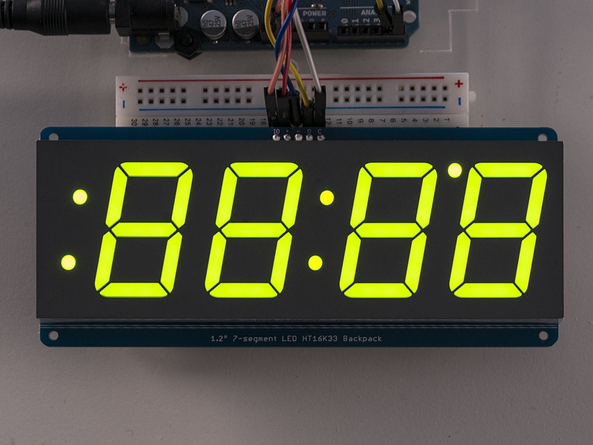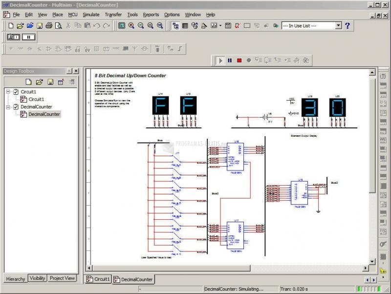


SSEG_AN0 – SSEG_AN3 – Four digital lines to control which of the four 7-segment displays to display.BTNO – Push button located on the DSDB board to reset the counter.SYSCLK_125MHZ – 125 MHz clock on the DSDB board.Select the connectors that you will be using on the DSDB board.Enter Counter_Example for the PLD subcircuit name and click Next.Select NI Digital Systems Development Board from the drop-down menu and click Next.Create a subcircuit that represents the PLD on the DSDB The PLD sub-circuit allows us to place the PLD code within a single component as if it was being run on the FPGA.


To achieve this we use a PLD sub-circuit. It places the PLD logic in place around the IO contained on the board. The top level schematic, as part of this project, allows for simulation. Refer to Multisim Won't Recognize My Digilent FPGA Board for more information. /programs/Vivado2014_4/data/xicom/cable_drivers//digilent/install_digilent.exe.LabVIEW 2015 SP1 FPGA Module Xilinx Tools Vivado 2014.4.Īn additional executable must be run. National Instruments Digital Systems Development Board.Multisim 14.0.1 or higher, Education Edition.You will need the following for this tutorial: This tutorial provides an example of how you can develop counters using the DSDB or any other Digilent FPGA board and use these to control the onboard 7-segment displays using Multisim and the PLD schematic.įor more details on installing and setting up the DSDB in Multisim, refer to the Getting Started with Digilent Boards in Multisim guide. Because of the inability of software-based simulations to meet the speed of hardware, gaining an understanding of timing can be difficult. Timing is a critical part of digital design. The PLD schematic allows educators and students to create graphical logic diagrams like those found in textbooks and deploy these to educational FPGA boards such as the Digital System Development Board (DSDB). Multisim’s Programmable Logic Device (PLD) schematic, along with support for leading Digilent teaching hardware allows students to put the fundamentals of digital theory into practice. Taking a hands-on approach to learning digital logic can be difficult without the need for students to learn complex hardware descriptive languages.


 0 kommentar(er)
